Problem Statement: Encountering insufficient load-bearing capacity in the original structure during a bridge erector modification can be a critical challenge for project managers, maintenance engineers, and construction firms operating in demanding regions like the UAE, Saudi Arabia, and other GCC countries.
Core Solution: The definitive approach involves a precise assessment of the original structure’s potential, followed by a closed-loop process of structural reinforcement, load optimization, and compliance verification. This methodology prevents the risks associated with blind reinforcement or simple component replacement, which can create new force imbalances. Follow these systematic steps for effective resolution.
The first and most critical phase is to establish an accurate baseline. This avoids costly guesswork and ensures reinforcements are both necessary and sufficient for GCC projects with specific material and safety standards.
1.1. Fill Data Gaps with On-Site Testing (Essential for Older Equipment)
If original design drawings or material certificates are missing, conduct non-destructive testing (NDT) to determine key parameters:
1.2. Conduct Full-Condition Mechanical Analysis
Model the new target working conditions—including increased beam weight, span, and working radius—using professional FEA software like ANSYS or Midas. The analysis must focus on:
1.3. Quantify the Specific Gap
The outcome must be a clear, quantified deficit. For example: “The stress in the lower flange of the main girder exceeds the allowable limit by 20%” or “The outrigger’s cross-sectional capacity has a 30% deficit.” This precision directs all subsequent reinforcement efforts.
Based on the quantified gap analysis, select a targeted reinforcement strategy that considers the structure’s condition and the goals of the modification project in the Middle East, where equipment often faces high-intensity use.
2.1. Reinforcement for Insufficient Main Girder Capacity
| Deficiency Scenario | Recommended Solution | Critical Implementation Details for Lasting Results |
|---|---|---|
| Overall strength near limit | Flange Plate Thickening + Web Stiffening | Weld thickened plates of identical material to the upper and lower flanges. Crucial: Ensure excellent weld fusion, apply pre-heating, and perform post-weld stress relief heat treatment. Add stiffeners to high-stress web zones. |
| Localized overstress (e.g., at lift points) | Local Reinforcement Plates | Size reinforcement plates according to stress calculations. Avoid over-reinforcement, which adds dead weight and can shift stress concentrations. |
| Presence of fatigue cracks | Crack Removal BEFORE Reinforcement | Mandatory first step: Completely remove cracks via carbon arc gouging or grinding, drilling a stop-hole at the crack tip. Never weld directly over an existing crack. |
2.2. Reinforcement for Insufficient Outrigger Capacity
Final Compliance Check: After reinforcement, update the mechanical model with the new reinforcement details and re-run the analysis to verify all stresses are within allowable limits under the new operational loads. A final round of NDT on critical welds is recommended.
Key Takeaway for Middle East Operators: In regions like the UAE and KSA, where project timelines and safety standards are stringent, this structured, evidence-based approach is not just best practice—it’s essential for ensuring the modified equipment’s reliability, safety, and compliance with local and international regulations, ultimately protecting your investment and worksite safety.
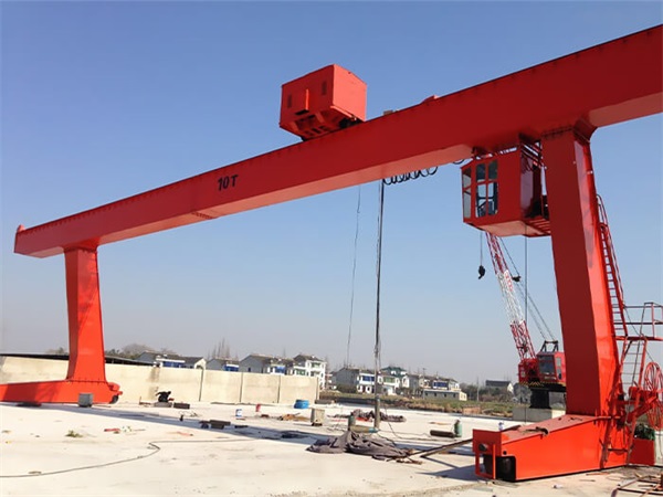
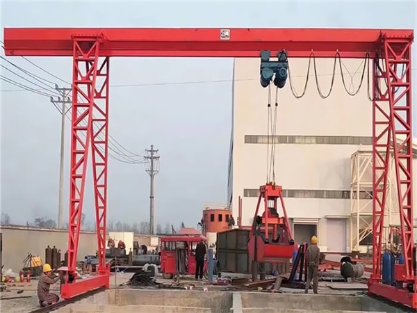
MH type electric hoist gantry crane is used together with CD MD model electric hoists.
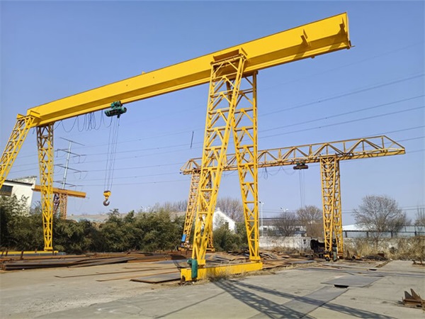
L Type electric hoist gantry crane match with CD1/ MD1, HC type Electric Wire rope hoist, to lifting and transporting the heavy materials, mainly use indoors and outdoors.
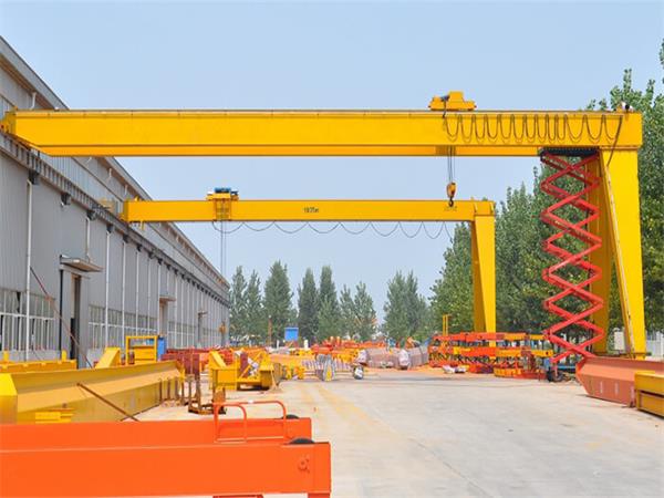
BMH Type Semi Gantry Crane is a bridge-type crane whose bridge is supported on the ground track through outriggers on both sides.
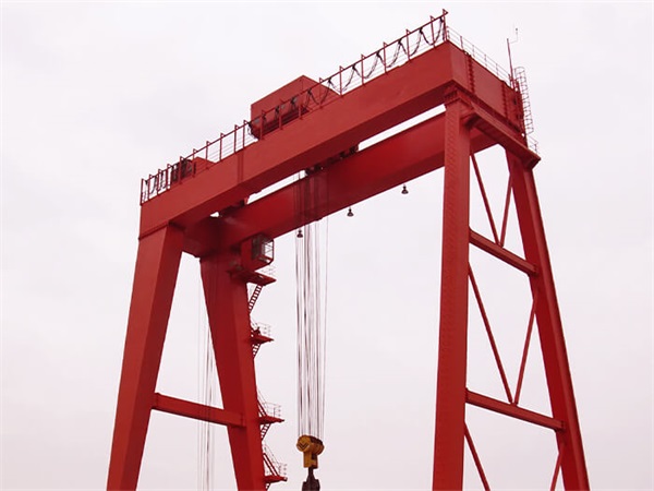
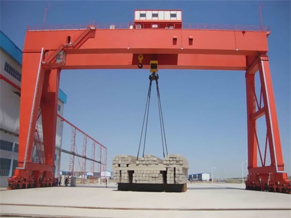
A-type Double Beam Hook Gantry Crane, It is mainly composed of a gantry (main beam, outriggers, lower beam, etc.), a lifting mechanism, a running mechanism and an electronic control part.
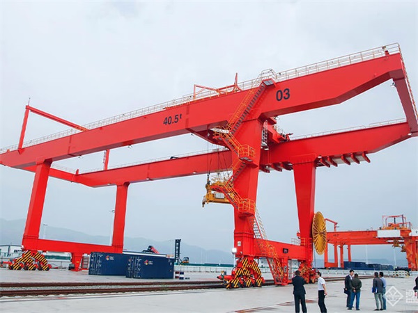
The rail-mounted container gantry crane (English abbreviation RMG) is one of the special machines for container yards.
MZ Type Double-beam Grab Gantry Crane are mainly used in conjunction with bridge cranes, port cranes, and winches. They are widely used in ports, power plants, docks, chemical industries, etc. to grab various types of loose accumulations, such as ore, coal, slag, etc.
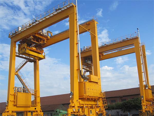
Winch Gantry Crane are used in open warehouses, windy areas, material stocks area, bridge building, concrete industry, cement plant, granite industry, construction industry, engineering industry, port, transportation, construction, dockyard, and other building sites for lifting and loading unloading objects.
U Type Subway Turn Slag Hook Gantry Crane also known as subway slag flipping machine, slag flipping gantry crane, slag flipping gantry crane, etc., is a specialized gantry crane used for excavation in subway and tunnel construction projects.
We design cranes that meet your needs. Whether you need to increase safety, maximize production capacity or reliability, or reduce costs, we deliver.